
Lab Station: Buffer tank
University of South-Eastern Norway (campus Porsgrunn) has 18 laboratory
buffer tanks, see Figure 1. The tanks are used in control courses in both
bachelor and master programmes in technology.
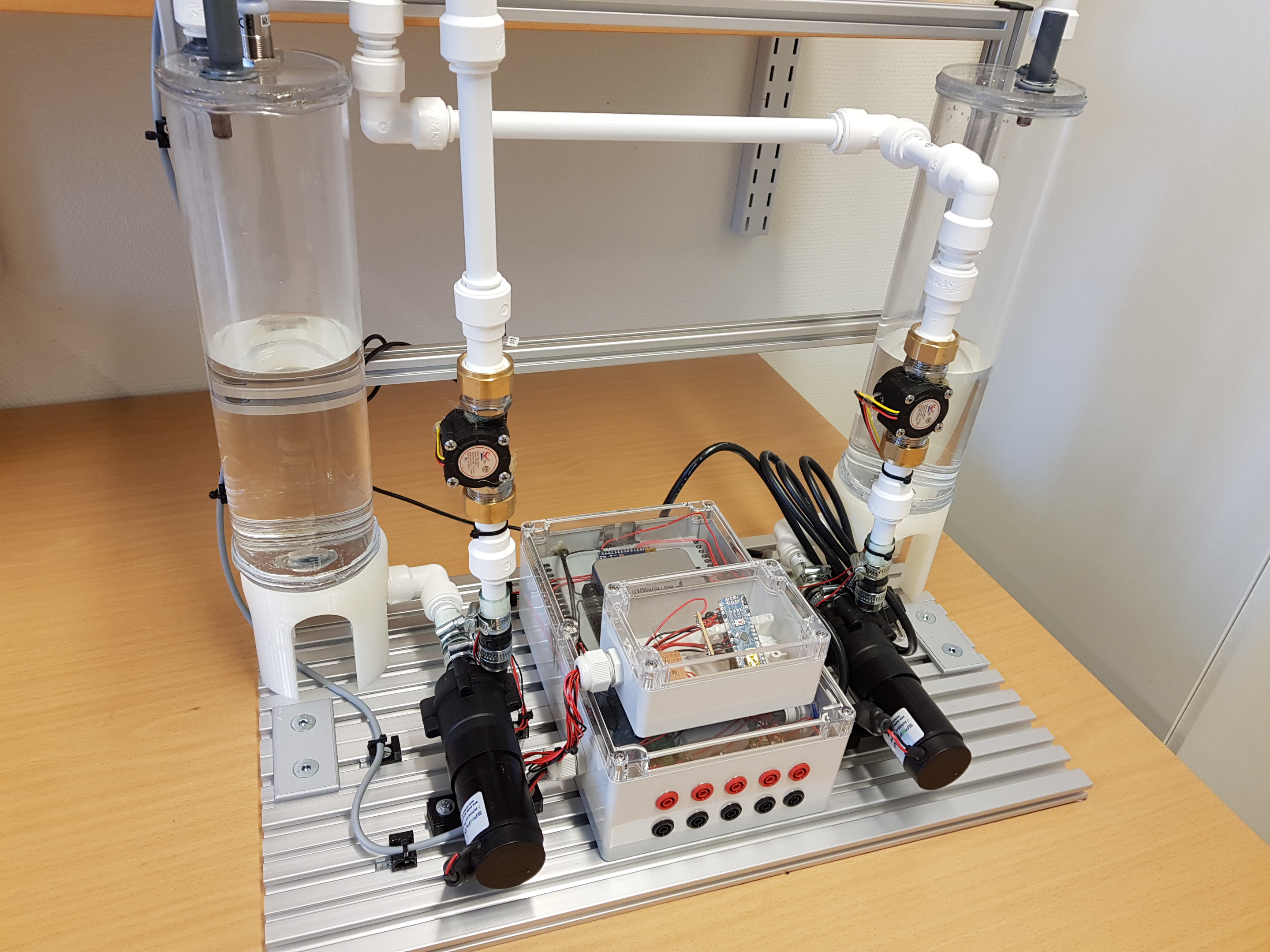
Figure 1: Buffer tank
Applications
Averaging level control is an important
part of several process systems. Some important practical examples are:
·
The equalization
or buffer magazine at the inlet of a wasteater treatment plant.
·
Oil/water
separators in the oil industry.
·
Water magazines
in hydropower systems.
Both the equalization magazine and the
separator can here be regarded as liquid buffer tanks. In both examples, the
level should be compliant to flow variations so that variations in the inflow
are damped through the tank, making the outflow considerably smoother than
the inflow. Smoother outflow is advantageous for the subsequent processes,
e.g. for the biological treatment processes and the oil production. The level
controller must be tuned for compliant (or soft, or sluggish) level control
so that the volume of the tank can absorb the inlet variations.
Technical description
Figure 2 shows a piping and instrumentation diagram (P&I D) of the
tank including a level control system.
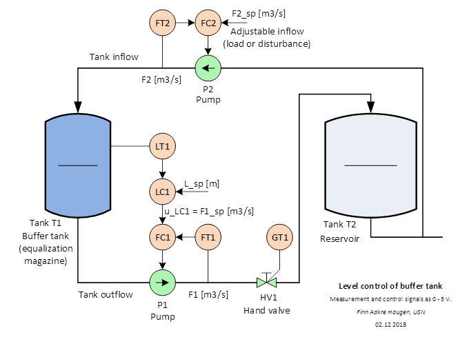
Figure 2: Piping and
instrumentation diagram (P&I D) of the buffer tank a level control
system.
The measurement signals (analog inputs) from the sensors LT1, FT1 and FT2
are voltage signals in the range 0 – 5 V.
The control signals (analog outputs) to the actuators pump P1and pump P2
are voltage signals in the range 0 – 5 V.
A built-in NI USB-6001 IO device handles the IO. This IO device can be
connected to a PC with a USB cable.
As an alternative to using the NI USB-6001 IO device, there are terminals
on the rig for direct analog IO.
Technical information
To appear.
Video presenting the buffer tank
To appear.
Level controller
The control signal generated by the level controller is a demanded
outflow:
u = F_out
The level controller may be a PI controller or some other controller.
Mathematical model
Mass balance of the water in the tank:
rho*A*dh_dt = rho*F_in – rho*F_out
where:
·
h [cm] is the water level in the tank.
·
F_in [cm^3/s] is water inflow.
·
F_out [cm^3/s] is water outflow.
·
A [cm^2] is cross-sectional area of tank.
·
rho [g/cm^3] is water density.
Cancelling out rho and solving for dh_dt gives the
dh_dt = (1/A)*(F_in - F_out)
Nominal values and ranges:
·
h_nom = 15. Range: 0 - 30.
·
F_in_nom = 50. Range: 0 - 100.
·
F_out_nom = 50. Range: 0 - 100.
·
A = 56.7.
·
rho = 1 (but its value is not needed).
How realize white noise in a simulator
If you want to include white process disturbance (noise) or white measurement
noise in a simulator of the buffer tank programmed in Python, you may use the
following information about how to generate uniformly distributed white noise
with specified standard deviation:
std_noise
= 0.01 # Standard deviation. 0.01 is
an example value. Select any other.
var_noise = std_noise**2 # Variance
ampl_noise = np.sqrt(3*var_meas_noise)
# Ampl of uniformly dist white noise. (np is numpy.)
v_k = np.random.uniform(-ampl_noise, ampl_noise, 1) # The noise (point value)
About
The project has been initiated by BSc Olav Vangen and Prof. Finn Aakre Haugen.
The construction as been accomplished by Olav Vangen, Cecilie Gløsmyr,
Fredrik Hansen, BSc Marius Bergflødt, and students at Skogmo high school.
Updated
21 February 2020 by Finn Aakre Haugen.
E-mail: finn.haugen@usn.no.
|