
Tekna Conference: Optimization of Oil and Gas Production Using Modern Information Technology, Nov 25-26, 2004:
Flash Course in PID Control
Application: Separator Control
By Finn Haugen (M.Sc.), TechTeach (and Telemark University College)
Thanks to Jostein Moe, ABB, for assisting in preparing the simulator of the separator train.
All course files zipped: tekna_olje_gass_281104.zip
Process Dynamics
Self regulating processes
Dynamic parameters:
- Process gain
- Time constant
Simulator: first_order_system.exe
Example: heated_tank.exe
Non self regulating processes - integrators
Dynamic parameter:
- Process gain
- Thinking in terms of first order system: What is the time constant of an integrator?
Simulator: integr.exe
Simulator: liquid_tank.exe
Flash course in PI(D) control
Let us work with this simulator: levelcontrol_chiptank.exe.
Finn H will explain terms simultaneously:
- Control objective (typical): Keep control error sufficiently small
- Control structure: Open loop control vs. closed loop control
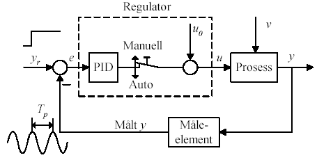
- Controller function: The PID controller. How are the various controller terms acting?
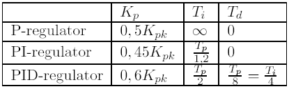
- Controller tuning: The Ziegler-Nichols' method (see figures below)
- Consequences of process variations
Ziegler-Nichols' method:
Are you a better controller than the PID controller? you_the_controller.exe
Let us also try feedforweard control: feedforward_control.exe
Litterature: Text book: PID Control
Separator control
The separator process
Simulator of a separator train: sepsim.exe. (Inspired by Vigdis.)
This simulator is based on the following simplifying assumptions wehich are assumed to have negligable impact on the responses/results:
- Immediate separation
- No emultion layer
- Constant gas pressure
- Equal density in water and oil
- Heat exchanger is represented by a flow dependent pressure drop
- Hydrocyclone is represented by a flow dependent pressure drop
Control objectives
Attenuate slug in the separator, but avoid trip at high/low level.
Open-loop control (blind control)
Run sepsim.exe with open-loop water level control in Separator 1. Successful?
Closed-loop/feedback control
Let us try sepsim.exe with
- P controller
- PI controller
for water level control.
Controller tuning
Skogestad's tuning method
Prof. Sigurd Skogestad has published tuning rules for several transfer function process models. The method is based on a specification of the setpoint step response. By doing some approximations (concering representing the time-delay term by a first order transfer function) and then solving for the controller in the control system model, the tuning rules are as shown in Table 7.1 in Ch. 8.2 in this extract from my text-book PID Control. (The coefficient k1 in Table 7.1 is due to a modification which I have introduced.)
Process gain variation
What may cause process gain variation?
Varying liquid surface area
The smaller area, the larger process gain (level becomes more sensitive to flow changes).
In a spherical or a cylindrical tank the liquid surface area varies with liquid level. This is illustrated in the simulator spheric_tank.exe.
Varying valve gain
A general valve equation:
![]()
q is flow. G is relative specific density compared to water. z is normalized valve opening.
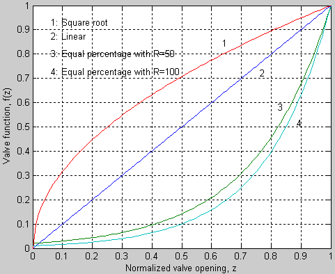
Below are shown various valve functions, f(z).
- Linear valve: f(z) = z
- Equal percentage valve: f(z) = R1-z where R is rangeability.
- Square root: f(z) = sqrt(z)
For all valves: Due to square root dependence of pressure drop, the valve gain of the valve itself (not installed valve) decreases as pressure drop decreases. For an installed valve, the pressure drop is decreased as the valve opening is increased, causing reduced valve gain. This can be coped with in different ways, as explained soon.
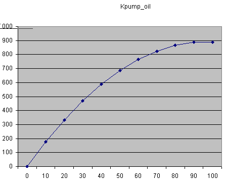
Varying pump gain
The pump characteristic, i.e. the flow [m3/h] as a function of the control signal [%] is shown in the figure below. The pump gain becomes smaller as the flow increases.
Consequences of process gain variation for the control system
The process gain is a factor in the control loop gain.
- Reduced process gain gives more sluggish control, and hence, slower disturbance compensation. Let us try this on sepsim.exe.
- In processes controlled by a PI controller, reduced process gain also causes reduced stability! Let us try this on sepsim.exe (oil level control of Separator 2).
- Increased process gain may cause stability problems.
How to cope with varying process gain
Conservative fixed controller tuning
Select fixed controller parameters which ensures performance at worst or most critical operating point. In most control systems, this means tuning at an operating point where process gain is at maximum. In the separator (integrator) it means tuning where process gain is at minimum, which corresponds to high flow.
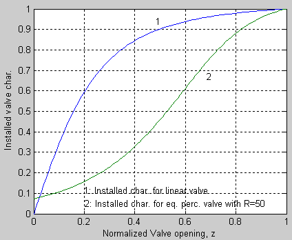
Using equal percentage valve in stead of linear valve
Equal percentage valves compensates (partly) for reduced valve gain caused by low pressure drop at high flows. Below are installed valve characteristics for linear valve and equal percentage valve. The latter is more linear than the linear valve (when installed)!
Let is try a linear valve and an equal percentage valve in sepsim.exe. High flow is assumed to be caused by a slug. Is there any diffference in control performance in using the different valves?
Continuous controller adjustment
- Gain scheduling based on a finite set of controller tunings. See Ch. 4.9.2 in this extract from PID Control. Let us try this simulator: gain_scheduling.exe.
- Model based controller parameter adjustment. See Ch. 4.9.3 in this extract from PID Control. In the separator this can be implemented by dividing the adjusting the valve control signal by the square root of the valve pressure drop. (This is not implemented in the simulator.)
Tips om reguleringskurs
- Basis reguleringsteknikk. Høgskolen i Stavanger 6. - 7. desember 2004
- Modellbasert PID-innstilling. Høgskolen i Stavanger 13. - 14. desember 2004
November 26 2004. Finn Haugen (finn@techteach.no)