 |
|
Introduction to
State Diagrams
by
5. February 2009
Introduction
This document gives an introduction to state diagrams. State diagrams can be used to define sequential control. State diagrams are quite similar to sequential flow charts (SFCs). SFC is standardized in the IEC 61131-3 standard (Intro på http://PLCopen.org), and is available as a progamming tool in most PLC systems, e.g. Mitsubishi PLCs, Simatic PLCs, etc. State diagrams are supported in e.g. State Diagram Toolkit of LabVIEW, the Stateflow Toolbox of Matlab/Simulink, and the Graph7 programming tool of Simatic PLCs.
The symbols and terms used in this document is not according to any specific standard, but they are similar to symbols and terms used in practical computer tools for creating state diagrams (some are mentioned above).
The elements of state diagrams
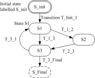
Figure 1 shows the elements of state diagrams. (The figure shows one example of a state diagram. Other diagrams may be simpler or more complicated.)

Figure 1: Elements of state diagrams: States and transitions
A state diagram represents a state machine. States of a state machine are either active or passive. Only one state is active at a time. The state machine always starts in a particular state defined as the initial state, and it ends (stops) after the final state. Special symbols or colors may be used for the initial state and the final state, cf. Figure 1.
Associated with a state are one or more actions. An action may be a control action executed by a controller. Actions may be listed as indicated below:
-
State 1 actions:
-
Action 1: Valve V1 is open;
-
Action 2: Motor M1 runs;
-
-
State 2 actions:
-
Action 1: Valve V1 is closed;
-
Action 2: Heater H1 is on;
-
The actions for a given state can be listed in a box attached to the state symbol, see Figure 2. However, the diagram may then become overloaded by symbols. Therefore, in more comprehensive state diagrams, it may be better to just list the actions in a separate document.

Figur 2: Action box listing actions for a state
Transitions brings the state machine from one state to another. A transition can go only from an active state which is presently active. A transition takes place only if its transition condition is TRUE. Transition conditions are in the form of logical expressions having value either TRUE or FALSE and may be listed as indicated below:
-
Transition T_Init_1: Button_start = ON.
-
Transition T_1_2: L1 > Level_High;
where Transition T_1_2 means the transition from state S1 to state S2. A transition condition may be written directly in the state diagram. For example, the expression
T_Init_1: Button_start = ON
may be written close to the transition arrow.
A transition may take place unconditionally, that is, it takes place immediately after the actions of the presently active state have been accomplished. Such unconditional transitions are named default transitions. The transition condition of an unconditional (or default) transition has permanent value TRUE, and it may be expressed as indicated below:
T_3_4: Default
or
T_3_4: TRUE
An example: Batch process control
Here is a simulator of a control system of batch process: Sequential control of a batch process.