A quick guide to National Instruments FieldPoint
I/O system
1 Introduction
2 Configuring I/O channels in Measurement &
Automation Explorer (MAX)
3 Renaming I/O channels
4 Testing I/O channels
5 Using FieldPoint I/O in LabVIEW
5.1 Introduction
5.2 Using FieldPoint functions for
I/O operations
5.3 Using OPC for I/O operations
1 Introduction
FieldPoint is a distributed modular I/O system produced by National Instruments. FieldPoint can be used with e.g. LabVIEW. If the FieldPoint hardware is equipped with an RT (Real-Time) module containing an embedded controller (microprocessor) running LabVIEW RT, you can download and run LabVIEW programs on the FieldPoint device. This document does not cover using FieldPoint for such embedded control.
Figure 1 below shows the FieldPoint rack at TechTeach's disposal. (National Instruments also delivers Compact FieldPoint which is a more recent product, but with similar capabilities as the original FieldPoint system.)
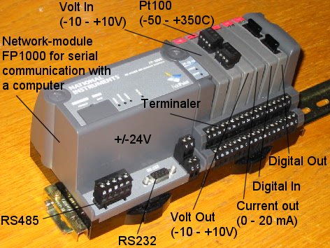
Figure 1: FieldPoint I/O system
The rack shown in Figure 1 contains the following modules:
- Network module FP1000 with a terminal for serial connection to a PC via RS232 serial cable. A DC power supply delivering a DC voltage between 12V and 24V, e.g. 24V, must be connected to the V and C terminals. The FP1000 module does not contain a micro processor, only AD- and DA converters and electronics implementing the serial communication. Thus the FP1000 module is not for embedded control. In stead, the application program must be implemented in LabVIEW.
- Terminal base module FP TB10 containing the following six
dual channel modules (each of these modules has two channels):
- AO (analog output) module for voltage output in the range +/- 10V
- Pt100 module for connecting Pt100 temperature sensors (these sensor are not shown in the figure)
- AO module for current output in the range 0 - 20mA
- AI module (analog input) for voltage input in the range +/- 10V
- DI (digital input) module
- DO (digital output) module
2 Configuring I/O channels in Measurement & Automation Explorer (MAX)
Before using the Fieldpoint I/O channels in LabVIEW, you must configure the I/O channels (and you should also test the channels) - using the Measurement & Automation Explorer (MAX) utility which is available via Start / Programs / National Instruments. (From FieldPoint 4.0 configuration of Fieldpoint is done using MAX, while this was previously done using the FieldPoint Explorer.)
Help about using MAX for configuring and testing FieldPoint is described in detail in the FieldPoint help in MAX. Go to Help / Help Topics / FieldPoint in MAX.
Figure 2 shows the dialog window where you configure the channels. As seen in the figure, this dialog window is available via My System / Devices and Interfaces in MAX.
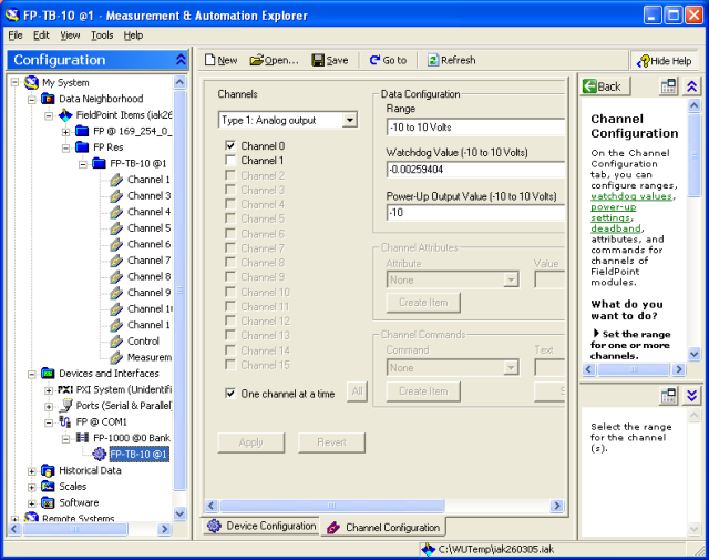
Figure 2: Dialog window for configuring I/O channels in MAX
The configurations can be saved in a *.iak file via the menu Tools / FieldPoint / Save in MAX.
3 Renaming I/O channels
Figure 3 shows the dialog window where you can rename I/O channels. This dialog window is available via My System / Date Neighborhood.
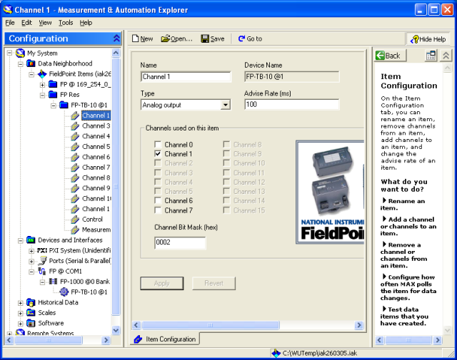
Figure 3: Dialog window for renaming I/O channels in MAX
4 Testing I/O channels
Figure 4 shows the dialog window where you can test I/O channels. This dialog window is available via My System / Date Neighborhood. You start monitoring I/O channel values (e.g. voltage values) by clicking the Start button, and you can write output values (e.g. a voltage for an analog output channel) by clicking the Write button. (Tip: A very simple way of testing that both analog output and analog input works correctly, is by connecting the input to the output.)
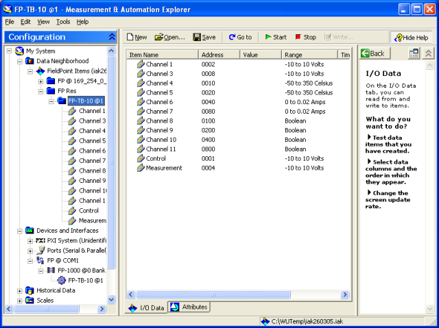
Figure 4: Dialog window for renaming and testing I/O channels in MAX
5 Using FieldPoint I/O in LabVIEW
5.1 Introduction
The I/O channels defined in FieldPoint Explorer can be used in your LabVIEW program (a VI) in two alternative ways:
- Using in-built FieldPoint functions available on the Functions palette in LabVIEW
- Using OPC (OLE for Process Control)
Both methods are described in the following. The methods are equally simple to use. Using FieldPoint functions may give faster data transfer, while OPC is more flexible since other software than LabVIEW can be used to address the FieldPoint I/O channels.
5.2 Using FieldPoint functions for I/O operations
The FieldPoint functions are available at the NI Measurements subpalette on the Functions palette, see Figure 5.
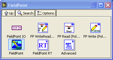
Figure 5: FieldPoint functions are available at the NI Measurements subpalette on the Functions palette
Figure 6 shows the front panel and Figure 7 shows the block diagram of iotest_fp_functions.vi where the FieldPoint functions FP Write and FP Read are used. (Alternatively, you can use the FieldPoint Express function available down left, and also the FP WriteRead function, for both Write and Read operations.) The Type input to the FP Read function is used to define the data type (here double floating point number).
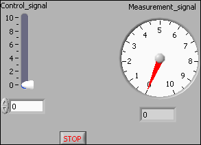
Figure 6: Front panel of iotest_fp_functions.vi
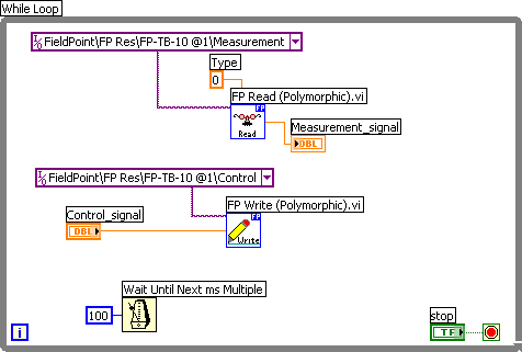
Figure 7: Block diagram of iotest_fp_functions.vi
The I/O FieldPoint constants in the block diagram in Figure 7 (the wide magenta rectangulars) contains at the right a browse button which you can use to browse to the FieldPoint I/O channel (or item or point), see Figure 8.
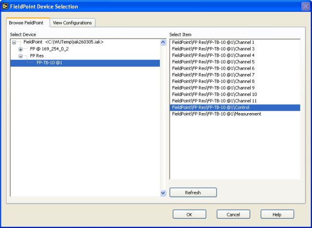
Figure 8: Browsing for FieldPoint I/O channels (or items or points)
5.3 Using OPC for I/O operations
OPC is short for OLE for Process Control which has become an important industry standard for connecting Windows programs (as LabVIEW) to I/O-equipment. All major automation vendors, as Siemens, National Instruments, Allen-Bradley, Honeywell etc., support OPC. (The home page of OPC is http://www.opcfoundation.org/ .)
The principle of OPC is as follows, cf. also the Figure 9.
- The OPC server of the I/O system (hardware) in use is assumed to be running. The OPC server is a service program running in the background of a PC. When using FieldPoint hardware the FieldPoint OPC server is automatically started as the FieldPoint Explorer is closed. The OPC server contains one item (or tag) for each of the channels configured in FieldPoint Explorer and the present value of the item.
- Any OPC client can read the value of an input item and can write a value to an output item on the OPC server. LabVIEW is one such OPC client.
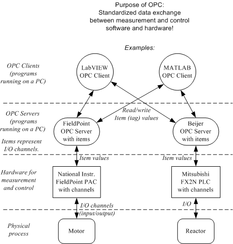
Figure 9: The principle of OPC
OPC can be applied for I/O in LabVIEW either programmatically or menu based. The latter is the simpler.
Figure 10 shows the front panel and Figure 11 shows the block diagram of iotest_opc.vi where the I/O operations are based on OPC.
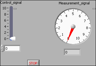
Figure 10: Front panel of iotest_opc.vi
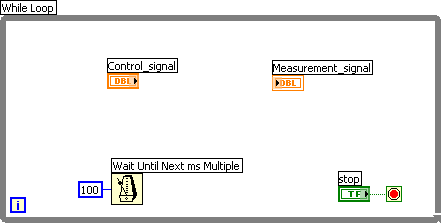
Figure 11: Front panel of iotest_opc.vi
The procedure for menu based OPC based I/O connection is described below.- Right-click on the terminal (in the block
diagram) that is to be connected to the proper item on the OPC
server. In Figure 10, this is either Control_signal or
Measurement_signal. In the context menu opened, select
Data operations / DataSocket Connection / Browse / Browse Measurement data.
Remember to select Publish if you want to write a value to the OPC server, and to select Subscribe if you want to read from the OPC server.
- Then browse to the proper item under the National Instruments.OPCFieldPoint OPC
server. Typically items appear organised in groups. As an example, Figure
12 shows how to connect the Control_signal terminal (variable) to the
Control item in
the Analog Output group on the OPC server.
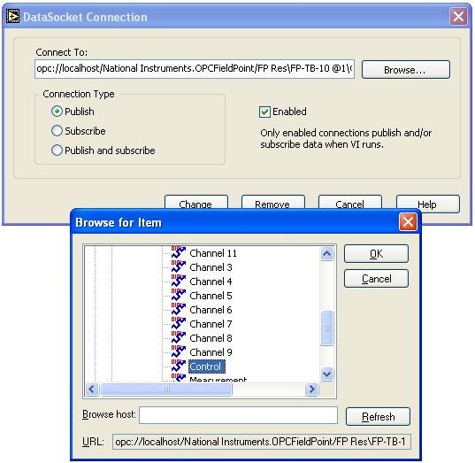
Figure 12: Connecting the Control_signal terminal (variable) to the Control item on the OPC server
As the VI runs the connection to the OPC server is indicated with a small rectangular lamp indicator at the upper right corner of the front panel element, see Figure 9. If the indicator is green the communication is ok. If it is red, something is wrong :-), and the error is displayed if you place the cursor over the indicator.
Additional information: FP2000 User Manual
October 28, 2005. Finn Haugen (finn@techteach.no).