A quick guide to National Instruments USB-6008
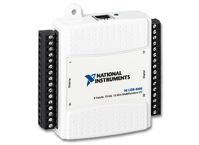
Figure 1: The USB-6008
1 Introduction
2 Checking if the USB-6008 device is
recognized by the PC
3 Configuring the USB-6008
4 Testing the USB-6008
5 Developing a LabVIEW VI
6 Multipe I/O
1 Introduction
The NI USB-6008 is a data acquisition and control device with the following features:
- Analog input (AI): 8 inputs with referenced single ended signal coupling or 4 inputs in differential signal coupling, see Figure 3 below. Software-configurable voltage ranges from ±1V to ±20V. Max sampling rate is 10kS/s (10000 samples per second). 12 bits AD converter. More information about signal coupling and signal ranges are given in Section 3.
- Analog output (AO): 2 outputs, see Figure 3 below. Voltage range is 0-5V (fixed). Output rate is 150Hz (samples/second). 12 bits DA converter.
- Digital input (DI) and digital output (DO): 12 lines which can be used as either DI or DO (configured individually), see Figure 4 below. These 12 lines are organized in ports: Input low is between -0.3V and +0.8V. Input high is between 2.0V and +5.8V.
- Counter: 32 bits.
- On-board voltage sources (available at individual terminals): 2.5V and 5.0V, see Figure 4 below.
- Power: USB-6008 is powered via the USB cable.
- Software: The necessary software is installed from the NI-DAQmx Base CD which is shipped with the USB-6008 device.
- Configuring and testing: USB-6008 can be configured using the NI-DAQmx Base Configuration Utility which is available via Start / Programs / National Instruments / NI-DAQmx Base. It can be tested using the LabVIEW file USB-600x Interactive Control.llb which is available via Start / Programs / National Instruments / NI-DAQmx Base. USB-6008 can not be configured and tested via the Measurement and Automation Explorer (MAX) utility.
- Documentation:
- USB-6008 Data sheet (which can be found by searching for USB-6008 at http://ni.com)
- Getting Started Guide which is available via Start / Programs / National Instruments / NI-DAQmx Base. (The present document should be sufficient to get started.)
- User Guide (which is also available via Start / Programs / National Instruments / NI-DAQmx Base). The User Guide shows in detail how USB-6008 should be connected to external signals (for measurement or control).
- Applications in LabVIEW: USB-6008 can be used with LabVIEW
by using functions on the NI Measurements /
DAQmx Base palette (on the Functions palette), see figure
below. USB-6008 channels can not be used with OPC.
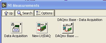
Figure 2: DAQmx Base palette (on the Functions palette)
- Examples: Several examples are available via Start / Programs / National Instruments / NI-DAQmx Base. (And one example is described in Section 5 of this document.)
Price: 1200 NOK. 145 USD.
Figure 3 below shows the analog I/O terminals with labels assuming differential signal coupling.
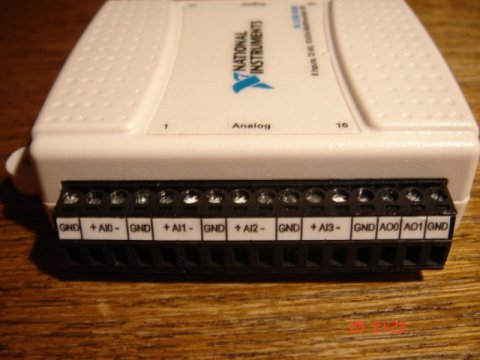
Figure 3: The analog I/O terminals with labels assuming differential signal coupling
Figure 4 below shows the digital I/O terminals with connections for the individual lines. P0 is port 0, and P1 is port 1. For example, P0.3 is line 3 in port 0.
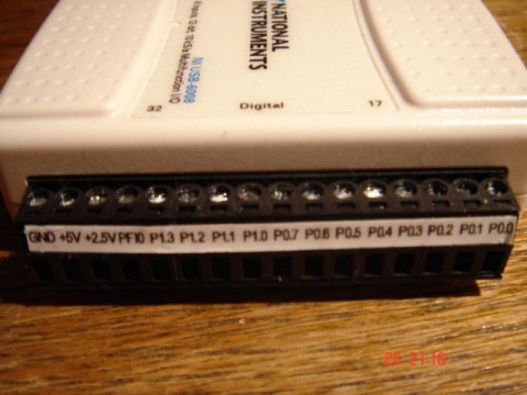
Figure 4: The digital I/O terminals
2 Checking if the USB-6008 device is recognized by the PC
To see if the USB-6008 device is recognized by the PC launch the NI-DAQ Base List Devices utility via Start / Programs / National Instruments / NI-DAQmx Base. Figure 5 shows the window thereby being opened. (The name VISA_USB6008 was defined by me using the MAX utility, but it is not necessary to define VISA names to use the USB-6008.)
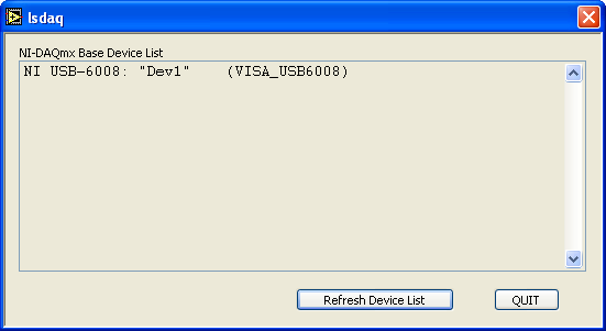
Figure 5: The NI-DAQ Base List Devices utility
3 Configuring the USB-6008
The USB-6008 can be configured using the NI-DAQmx Base Configuration Utility which is available via Start / Programs / National Instruments / NI-DAQmx Base. See the figure below.
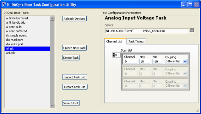
Figure 6: The NI-DAQmx Base Configuration Utility
Using NI-DAQmx Base Configuration Utility you define tasks. You use tasks in your LabVIEW application to refer to the I/O operations. A task is a collection of definitions expressing various aspects of the signal input or signal output operation to be executed by the I/O device. A task definition may include the following (here an analog input task is assumed):
- Task name
- Channel number, e.g. 0, 1, 2 etc.
- Maximum and minimum value of the signal range. This is applicable only to analog input in differential coupling (see below).
- Type of signal coupling:
- Referenced single ended which means that all channels have the same ground. The signal range with referenced single ended coupling is ±10V (fixed).
- Differential which means that each channel has its own (individual) ground. Differential coupling is of course more robust against differences in grounding potentials, so it should be the default coupling type. The signal ranges with differential coupling are ±20V, ±10V, ±5V, ±4V, ±2.5V, ±2V, ±1.25V, ±1V. Note that the maximum voltage on any one pin is ±10V with respect to GND. For example, if AI1 is +10V and AI5 is –10V, then the measurement registered by USB-6008 is +20V.
- Task timing:
- Continuous which can be used in continuous I/O (stopped at any time by the application, e.g. when the user clicks a stop button on the LabVIEW front panel)
- Finite which can be used when there is a predefined number of continuous I/O operations, e.g. 1000 samples.
- On Demand which can be used single I/O operations, as in manual control or in feedback control of a process.
The figure above shows the settings of the aitask task. (This task was defined by me.) The task listed above aitask and aotask are predefined tasks.
To create a new task, press the Create New Task button, causing the dialog window shown in the figure below to be opened.
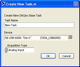
Figure 7: The Create New Task dialog window
You must define one task for each of the input or output operations, i.e. one task for a particular analog input operation and one task for a particular analog output operation.
Once you have completed defining the task(s) you click the Save & Exit button.
4 Testing the USB-6008
The USB-6008 can be tested using the LabVIEW file USB-600x Interactive Control.llb which is available via Start / Programs / National Instruments / NI-DAQmx Base, see the figure below.
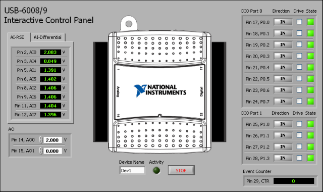
Figure 8: The USB-600x Interactive Control.llb can be used for testing the device
5 Developing a LabVIEW VI
In the following a concrete example VI with analog output and analog input is described. The VI was used to control this DC motor using analog output and to measure the tachometer voltage using analog input. (In this example, no feedback control system is implemented. Only manual control or open loop control is implemented.)
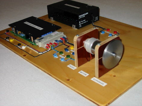
The figures below show the front panel and the block diagram of ao_ai.vi which implements analog input and analog output.
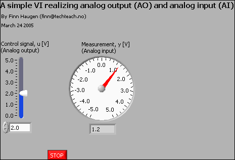
Figure 9: Front panel of ao_ai.vi
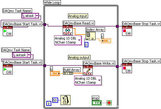
Figure 10: Block diagram of ao_ai.vi
Comments:
-
The various DAQmxBase functions used in the block diagram exist on the NI Measurements / DAQmx Base palette (on the Functions palette) in LabVIEW.
-
The two tasks aotask and aitask have been defined using the NI DAQmx Base Configuration Utility, cf. Section 3.
-
The DAQmxBase Start Task function must be invoked once, before the While loop starts. The DAQmxBase Stop Task function must be invoked once, after the While loop has stopped.
-
The DAQmxBase Read function reads the voltage value of the analog input channel as defined in aitask. The field attached to the bottom of the function is the Polymorphic VI Selector from which you can select which type of signal read the function will perform. The choices are Analog, Digital, Counter, and More. Note that the read signal is in the form of an 1D (one dimensional) array. This is because the function can be used to read several inputs simultaneously. The Index Array function is used to extract or index the scalar input having array index 0 (i.e. the input is represented by the first element of the array).
-
The DAQmxBase Write function writes the voltage value of the analog output channel as defined in aotask. Via the Polymorphic VI Selector you can select which type of signal write the function will perform. The choices are Analog, Digital, Counter, and More. Note that the written signal is in the form of an array. This is because the function can be used to write several outputs simultaneously. The Build Array function is used to construct this array, which in this example has only one element.
-
This VI runs with cycle time of 50ms.
6 Multiple I/O
Section 3 shows to configure tasks for single I/O operations, and Section 5 shows how to use such single I/O channels in your LabVIEW program. However, the USB6008 has several input channels and several output channels. Assume as an example that your application requires two analog inputs. You should not create one task for each input (in the NI-DAQmx Base Configuration Utility). Instead, you create one analog input task covering both I/O channels. This is done by simply expanding the array in which the channels are defined, see Figure 11.
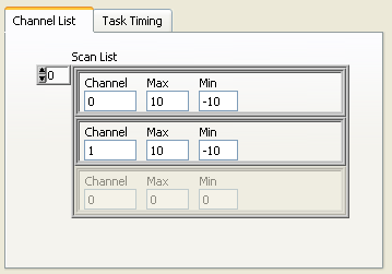
Figure 11: Configuring one analog input task for two AI channels in the NI-DAQmx Base Configuration Utility
In your LabVIEW program you use the Index Array function to address each of the channels, see Figure 12.
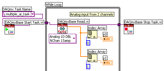
Figure 12: In your LabVIEW program each of the channels are addressed using the Index Array function
More free tutorials are available at http://techteach.no.
December 8, 2005. Finn Haugen (finn@techteach.no).