A quick guide to National Instruments USB-6009 and USB-6008 multifunction I/O devices

Figure 1: The USB-6009 (USB-6008 is similar)
I suggest using this (newer) video for learning about the NI USB-6008/6009 devices. The video replaces the present document.
1 Introduction
2 Labeling the I/O terminals
3 Connecting the USB-6009 to the PC
4 Testing and configuring the USB-6009 in MAX.
Video included!
5 Using the USB-6009 in LabVIEW.
Video included!
1 Introduction
This document is a quick guide to NI USB-6009 multifunction I/O device, and to the similar NI USB-6008 device. In the following only the name USB-6009 is used. Special USB-6008 features are described separately.
The NI USB-6009 is a USB based data acquisition (DAQ) and control device with analog input and output and digital input and output. The price is 2100 NOK. The NI USB-6008 is a similar, but somewhat simpler (and cheaper) device.
The main features of NI USB-6009 are as follows (the USB-6008 features which differs, are also given):
- Analog input (AI): 8 inputs with referenced single ended signal coupling or 4 inputs with differential signal coupling. Software-configurable voltage ranges: ±20V, ±10V, ±5V, ±4V, ±2.5V, ±2V, ±1.25V, ±1V. Max sampling rate is 48kS/s (48000 samples per second). 14 bits AD converter (USB-6008: 12 bits).
- Analog output (AO): 2 outputs. Voltage range is 0 - 5V (fixed). Output rate is 150Hz (samples/second). 12 bits DA converter.
- Digital input (DI) and digital output (DO): 12 channels which can be used as either DI or DO (configured individually). These 12 channels are organized in ports, with Port 0 having lines 0, .., 7, and Port 1 having lines 0, .., 3. Input low is between -0.3V and +0.8V. Input high is between 2.0V and +5.8V. Output low is below 0.8V. Output high is above 2V (with open-drain and push-pull as options). (USB-6008 has only open-drain output.)
- Counter: 32 bits. Counting on falling edge.
- On-board voltage sources (available at individual terminals): 2.5V and 5.0V
- Power: USB-6009 is powered via the USB cable.
- Configuring and testing: USB-6009 can be configured and tested using MAX (Measurement and Automation Explorer) 4.0, which is installed with NI-DAQ 8.0. The latter is available on the CD shipped with the device, and can alternatively be downloaded for free from http://ni.com (the NI-DAQ 8.0 file is approximately 0,5GB).
- Application software: LabVIEW, C, or Visual Studio. Platforms: Windows, Mac, Linux. The present document gives an example of how to use USB-6009 in LabVIEW.
- Documentation: The following relevant documents can be
found at http://ni.com:
- USB-6009 product home page
- USB-6009 Data Sheet (which is available from the product home page)
- Getting Started Guide: NI-DAQmx for USB Devices (which is available from the product home page). This document explains how to test the device in Measurement and Automation Explorer (MAX).
- USB-6008/6009 User Guide and Specifications (which is available from the product home page). This document shows in detail how USB-6008 must be connected to external signals for measurement or control.
2 Labeling the I/O terminals
Before you start using the USB-6009, you should attach labels to the analog and digital terminals. Figure 2 below shows the analog I/O terminals with labels assuming differential signal coupling. (In general, differential signal coupling is preferrable to single ended coupling due to better DC noise suppression).
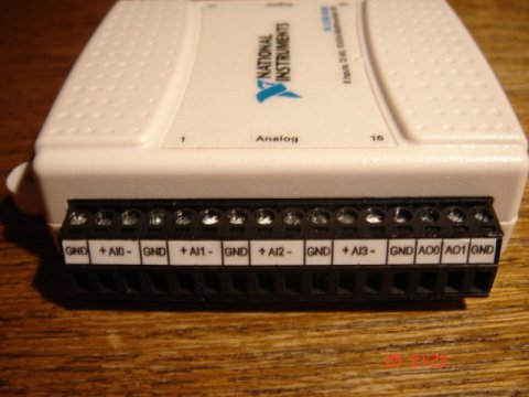
Figure 2: The analog I/O terminals with labels assuming differential signal coupling
Figure 3 below shows the digital I/O terminals with connections for the individual lines. P0 is port 0, and P1 is port 1. For example, P0.3 is line 3 in port 0.
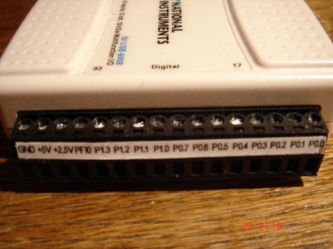
Figure 3: The digital I/O terminals
The USB-6008/6009 User Guide and Specifications describes the I/O terminals in detail.
3 Connecting USB-6009 to the PC
The first time you connect the USB-6009 to the PC, the Windows Hardware Installer Wizard will open, see Figure 4.
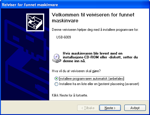
Figure 4: The Windows Hardware Installer Wizard (in Norwegian version...)
In this dialog window, select the option for automatic install.
Then, the wizard searches the PC for the necessary driver software for the USB-6009. This driver software was installed along with the installation of the NI-DAQ software.
When the wizard has finished the installation of the driver software, the USB-6009 is ready for use (after you click Finish (Norwegian: Fullfør)), see Figure 5.

Figure 5: The wizard has finished the installation of the driver software, and the USB-6009 is ready for use, after you click Finish (Norwegian: Fullfør)
If you disconnect the USB-6009 from your PC, and then connect it again later, the New Data Acquisition Device dialog window pops up, giving you several options, see Figure 6.
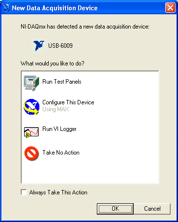
Figure 6: The New Data Acquisition Device dialog window
Probably, you will now want to test and configure the USB-6009 in MAX. You may therefore select one of the upper two options. However, here I assume that you select Cancel. Thus, we will open MAX in the ordinary way via the Start menu on the PC.
4 Testing and configuring the USB-6009 in MAX
|
Here is a video that shows the steps: max.avi (9 minutes, 104 MB) |
Testing the USB-6009 in MAX
Before you start to use the USB-6008 in an application, you should test the device in the MAX utility, which is available via Start / Programs / National Instruments. Figure 7 shows MAX.
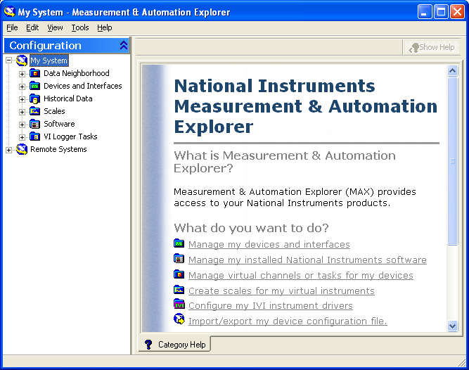
Figure 7: MAX (Measurement and Automation Explorer)
In the MAX window, expand the Devices and Interfaces item, see Figure 8. .
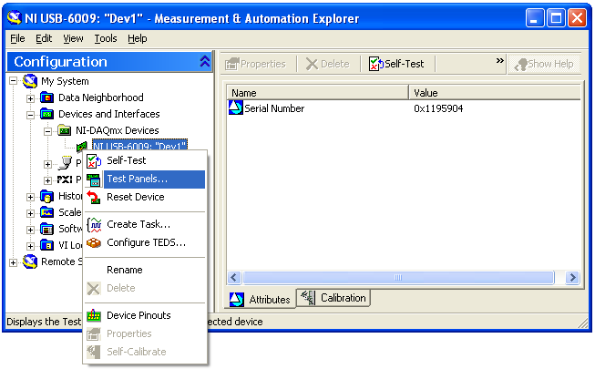
Figure 8: The Devices and Interfaces item
If MAX recognizes the USB-6009, the device appears under NI-DAQmx Devices.
Assuming that MAX recognizes the device, you can now run a self-test of it by selecting Self-Test in the menu.
Hopefully the self-test passes without errors. Then, you should test the individual channels of the USB-6009 to check that the input signals are detected correctly by the USB-6009, and that the output signals generated by the USB-6009 have correct values. This I/O can be tested in several ways, depending on which channels you actually want to test. Here, let us test analog output channel 0 (AO0) and the analog input channel 0 (AI0) to see if they work correctly. We will perform a very simple test, which is sufficient if we are to check that both AO0 and AI0 work correctly. The test procedure, which is denoted loopback, is to connect the AI0 channel to the AO0 channel. Then we generate some legal voltage at AO0. If AI0 detects the same voltage, we know that both AO0 and AI0 works. (We may then repeat this procedure for other channels.) If for some reason AI0 detects some other voltage than the value we set for AO0, then there is an error in either the AI0 channel or in the the AO0 channel, and further investigations are necessary.
To prepare for the loopback test, we wire together AI0 and AO0. To see the terminals of the USB-6009, select Device Pinouts in the menu shown in Figure 8. The terminals or pins are shown in the NI-DAQmx Device Terminals window, see Figure 9.
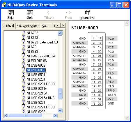
Figure 9: The terminals or pins are shown in the NI-DAQmx Device Terminals window
Figure 10 shows the AI0 and AO0 channels wired together.

Figure 10: To prepare for the loopback test, AI0 and AO0 are wired together.
To actually perform the loopback test, right-click on the device labeled NI USB-6009: "Dev1" in MAX, and then select Test Panels, thereby opening the Test Panels. In the Test Panels window, select the Voltage Output tab, see Figure 11.
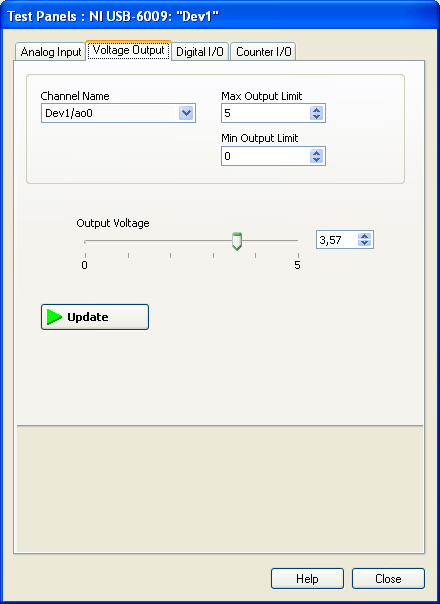
Figure 11: The Voltage Output dialog window in the Test Panels window
In the Voltage Output dialog window, select any voltage between 0V and 5V. In Figure 11, an output voltage of 3.57V is set.
Next, click the Analog Input tab in the Test Panels window, see Figure 12. You may deselect Auto-scale chart in the window.
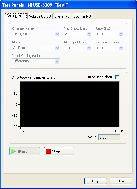
Figure 12: The Analog Input dialog window in the Test Panels window
If the channel testing passed without problems, you may end the testing session by setting 0V on the output (in the Voltage Output window).
The Analog Input window should indicate the same (or almost the same) voltage as is set out on AO0. There may be a small difference between the values due to the limited resolution in the DA-converter (digital-to-analog) and in the AD-converter (analog-to-digital).
Configuring the USB-6009 in MAX
Introduction
After the testing has passed successfully (cf. Section 4, above), you must configure the USB-6009 in MAX. In the folllowing it described how to create tasks for the analog input and the analog output operations. These tasks are referred to in the application program, e.g. LabVIEW. In general, a task represents the configuration of the signal input or signal output operation to be executed by the I/O device. Creating tasks is a general feature of the MAX utility, i..e. tasks are used also for configurating other I/O devices than the USB-6009.
In general, a task can contain one or more global or local virtual channels, and one such virtual channel is based on one physical channel (having e.g. a screw terminal on the I/O device). A local virtual channel exists only within it's parent task, while a global virtual channel may be used in several tasks. If a global channel is reconfigured, all tasks which involve that global channel are updated accordingly. All these items, i.e.
- tasks,
- local and global virtual channels,
- physical channels,
can be configured in MAX. Tasks and virtual channels can be given any name (e.g. task_motor and meas_speed, respectively), while the physical channels will have predefined names (e.g. ai0, ai1, ao0, ao1).
Configuration of an analog input task
See Figure 8. Selecting Create Task in the menu opens a window where you can select the measurement type, see Figure 13.
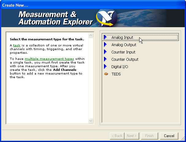
Figure 13: Window where you select the measurement type
In our case, in Figure 13 we select Analog Input (later we will select Analog Output). This opens the window shown in Figure 14 where you can select the measurement type from a list.
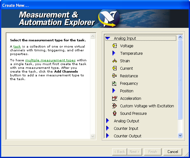
Figure 14: A list of options for the measurement type
From the list of measurements type, we select in our case Voltage, which opens the window shown in Figure 15 where you can enter the name of the task.
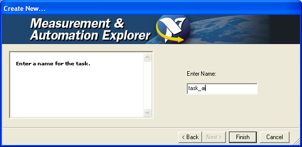
Figure 15: Window where you can enter the name of the task
By clicking the Finish button in the window shown in Figure 15, the window shown in Figure 16 is opened where you can select the physical channels for your task.
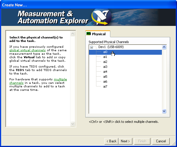
Figure 16: Selecting physical channel for the task
In the window shown in Figure 16, we select ai0, which opens the window shown in Figure 17.
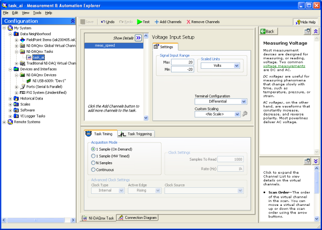
Figure 17: Window for configuration of the analog input associated with task_ai0
The window shown in Figure 17 has several items. Most of these are described in the following. Note that information about an item in the window is shown in the sub-window down right (see Figure 17).
- Virtual channel list, which is the area having the Show Details button at the top. By default, the virtual channel name of an analog input channel is Voltage, Voltage1 etc. However, you can rename the channel by right-clicking the virtual channel name, and then selecting Rename from the context menu. This has been done in Figure 17, where the default name Voltage has been renamed to meas_speed. You can also, by right-clicking on the virtual channel name, define a (local) virtual channel to become a global virtual channel, which means that the channel can be a part of several tasks at the same time.
- Terminal Configuration:
- Referenced single ended which means that all channels have the same ground. The signal range with referenced single ended coupling is ±10V (fixed).
- Differential which means that each channel has its own (individual) ground. Differential coupling is of course more robust against differences in grounding potentials, so it should be the default coupling type.
- Custom Scaling: This gives you the possiblility to define a scaling of the raw measurement signal from the measurement unit (Volts in the USB-6009) to some other unit (e.g. cm). It is the scaled value (e.g. cm) which becomes available in the application software (e.g. LabVIEW). If you select No Scale, it is the numeric value of raw measurement signal (V) that becomes available in the application software.
- Signal Input Range: Here you select the input range. The allowable signal ranges with differential coupling are ±20V, ±10V, ±5V, ±4V, ±2.5V, ±2V, ±1.25V, ±1V. Note that the maximum voltage on any one pin is ±10V with respect to GND. For example, if AI1 is +10V and AI5 is –10V, then the measurement registered by USB-6008 is +20V.
- Scaled Units: The only option for USB-6009 is Volts.
- Task Timing: : Under Acquisition Mode you have four options which are more or less self-explanatory. For example, if the USB-6009 is used to read a measurement signal and this signal is fed into a controller which calculates a control signal as a function of the measurement signal, then you will use the option 1 Sample (On Demand).
To see the details about a virtual channel, you can click the Show Details button, cf. Figure 17. This shows the physical channel associated with the virtual channel, see Figure 18.
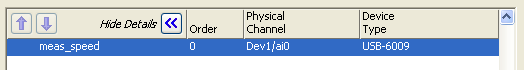
Figure 18: Details about a virtuel channel can be shown/hidden using the Show Details/Hide Details button
Configuration of an analog output task
Above we created a task for an analog input. You can create a task for analog output in the same way, that is, by selecting Create Task in the right-click menu of the USB-6009 device as it appears under Devices and Interfaces, see Figure 8. Figure 19 shows the resulting task configuration window for the task_ao task.
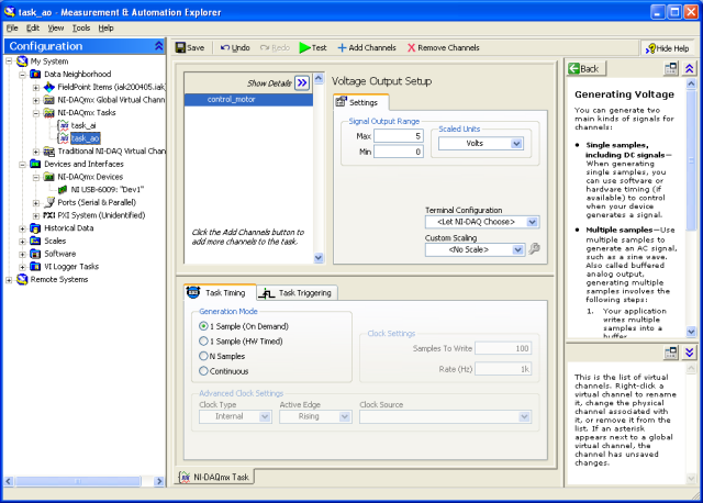
Figure 19: The task configuration window for the task_ao task.
As shown in Figure 19, the tasks which have been configured, appears under Data Neighborhood/NI-DAQmx Tasks.
Saving the configuration
The configuration can be saved using the Save button, see Figure 19. The most recent settings are saved, and are loaded the next time MAX is opened. You can also export the conguration to a file via the menu File / Export. This menu also has an import option.
After you have finished configuring the device in MAX, you should close MAX (otherwise an error may occur).
5 Using USB-6009 in LabVIEW
|
Here is a video that shows the steps: labview_io.avi (14 minutes, 125 MB) |
The functions needed for programming I/O operations for USB-6009 are found on the Functions / NI Measurements (Measurements I/O in LabVIEW 8) / DAQmx palette (not DAQmx Base, if you happen to have the latter installed). Figure 20 shows the contents of the DAQmx palette.
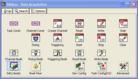
Figure 20: The DAQmx palette on the Functions palette
Single sample at one channel
The VI ao_ai.vi is an example of how to read in one single sample from one channel, and how to write out one single sample to one channel. The figures below show the front panel and the block diagram of ao_ai.vi. (In this example the analog output channel AO0 and the analog input channel AI0 are connected, as in the loopback testing procedure described earlier.) Note that the In Range and Coerce function is used to limit the numerical value which is the input to the DAQmx Write function. Here the value is limited between 0 and 5. If you had written a value outside this range to the DAQmx Write function you would get an error due to signal limitations function (it can only generate voltage outputs between 0 and 5 volts).
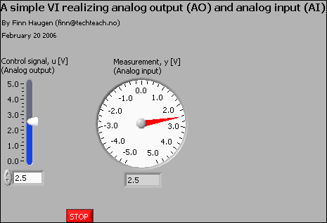
Figure 20: Front panel of ao_ai.vi
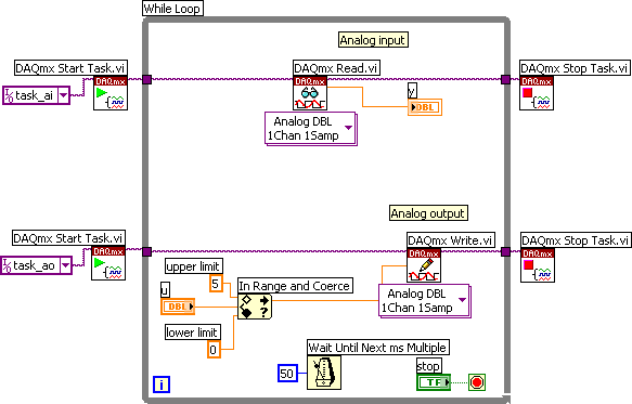
Figure 21: Block diagram of ao_ai.vi
Comments:
-
The two tasks task_ao and task_ai have been defined in MAX, cf. Section 5.
-
The DAQmx Start Task function must be invoked once, before the While loop starts. The DAQmx Stop Task function must be invoked once, after the While loop has stopped. Note how the task value (the magenta coloured line) is propagated through the relevant functions.
-
The DAQmx Read function reads the voltage value of the analog input channel as defined in task_ai. The field attached to the bottom of the function is the Polymorphic VI Selector from which you can select the type of data the function will read.
-
The DAQmx Write function writes the voltage value of the analog output channel as defined in task_ao. Via the Polymorphic VI Selector you can select the type of data the function will write.
-
This VI runs with a cycle time of 50ms.
If you want to implement writing data to a log file in your VI, take a look at my LabVIEW Tutorial.
Single samples at multiple channels
In MAX you can define tasks which involves I/O on several (virtual) channels at a time. This is done by selecting Add Channels in MAX, see Figure 17.
How do you address the channels of such a multi-channels task in LabVIEW? You can use the Index Array function (on the Array palette). Figure 22 and Figure 23 shows the front panel and the block diagram of multiple_ai.vi which is a simple example of multiple analog input.
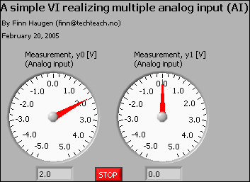
Figure 22: Front panel of multiple_ai.vi
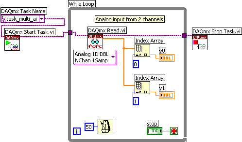
Figure 22: Block diagram of multiple_ai.vi
More free tutorials are available at http://techteach.no.
Updated 17 April 2008. Finn Haugen (finn@techteach.no).