DC-Motor
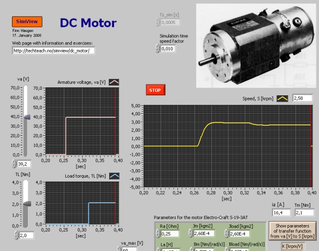
Snapshot of the front panel of the simulator:

- What is needed to run the the simulator? Read to get most recent information!
- Tips for using the simulator.
- The simulator: dc_motor.exe . The simulator runs immediately after the download by clicking Open in the download window. Alternatively, you can first save a copy of the exe-file on any directory (folder) on your PC and then run the exe-file, which starts the simulator.
Introduction
DC-motors are used in many servo mechanisms. Compared to other electric motors, DC-motors are easy to model mathematically.
The DC-motor simulated is the Electro-Craft S-19-3AT which is an armature controlled DC-motor. The motor parameters are given on the front panel of the simulator.
Theory
In the expressions below the following quantities are used: S is rotational speed. va is armature voltage. ia is armature current. Tf is friction torque. TL is load torque. J is the sum of the intertias of the motor and the load, i.e. J = Jmotor + Jload. B is the sum of the damping coefficients of motor and load. La is the armature inductance. Ra is the armature resistance. Ke is the voltage constant (the so called back-emf constant). KT is the torque constant.
Dynamic model (differential equation)
A mathematical model of the motor can be found from the Kirchhoff's voltage law on the armature circuit and the torque balance of the mechanical rotation:
Kirchhoffs voltage law yields
(1) Ladia/dt = va - Raia - KeS
Torque balance yields
(2) JdS/dt = KTia - BS - Tf - TL
Transfer function model
By taking the Laplace transform of the model above we will find the following transfer function from armature voltage va to speed S:
(3) S(s)/va(s) = H(s) = K/[(s/w0) + 2z(s/w0) + 1]
where the parameters are as follows:
Gain:
(4) K = Kt/(KtKe+BRa) [rpm/V]
Relative damping factor:
(5) z = 0.5*(JRa+BLa)/[sqrt(JLa(KtKe+BRa))]
Undamped resonance frequency:
(6) w0 = sqrt[(KtKe+BRa)/(JLa)] [rad/s]
Static model
By setting the derivatives in (1) and (2) equal to zero and eliminating ia, we get the following static model (all variables are assumed to have constant values):
(7) S = [Kt/(KtKe+BRa)]va - [Ra/(KtKe+BRa)](Tf + TL)
Tasks
- Assume that the armature voltage va is 30 volt and that
the motor parameters have values equal to the default values (can be
recalled using the menu Operate / Reinitialize All to
Default on the front panel of the simulator).
- Find the static speed (using simulation).
- Calculate the static speed from the static model (7). Is the answer in accordance with the result found in task 1a?
- See equation (5). How are the relative damping factor and the undamped resonance frequency changed if the total inertia J increases? Is the result confirmed in a simulation (qualitatively)?
- Confirm both from the model and from simulations that the statis speed is independent of the inertia.
- Use the default values of the motor parameters.
- What is the value of w0 (you can read it off from the simulator front panel)?
- In general the response time (the 63% raise time of the step response) of a second order system is approximately equal to 1.5/w0 [sec]. Calculate from this the response time of the motor. Is the result in accordance with a simulated step response?
Updated 2 September 2017. Developed by Finn Haugen. E-mail: finn@techteach.no.
