Measurement filter
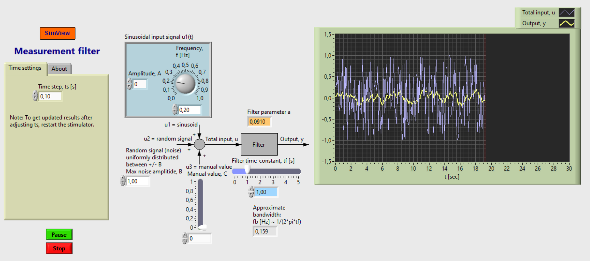
Snapshot of the front panel of the simulator:

- What is needed to run the the simulator? Read to get most recent information!
- Tips for using the simulator.
- The simulator: measurement_filter.exe
Aims
The aims of this simulator are:
- Demonstrate how a measurement filter attenuates a sine signal (noise).
- Demonstrate how a measurement filter attenuates random signal (random noise).
Motivation
Measurement filters are frequently needed in practical application based in some processing of measurements. This is because all practical measurements are noisy. Typically the noise is approximately a random signal. The filter is used to attenuate the noise.
One very important application is in a control system. The process measurement (temperature, level, pressure, speed etc.) always contains some noise. If the noise is not attenuated it will propagate through the controller and cause abrupt (noisy) variations in the control signal, causing excessive wear of the actuator (pump, valve, motor).
Description of the system that is simulated
Filter algorithm
y_k = (1 - a)*y_km1 + a*u_k
where:
y_k is present filter output, y_km is previous filter output ("km1" means k-1), u_k is present filter input.
a = ts/(tf + ts)
where: ts [s] is time step (or sampling time). tf [s] is filter time constant, or time window of moving averag filter.
Input signals to the filter
The input signal to the filter consists of three additive terms:
- A sinusoidal signal
- A random signal (white noise)
- A constant (or bias)
Each of these signals can be deactivated (removed). The (total) input and the output signals are plotted in real time in a chart.
Updated 2 September 2017. Developed by Finn Haugen. E-mail: finn@techteach.no.
