![]()
Feedforward Control of Liquid Level
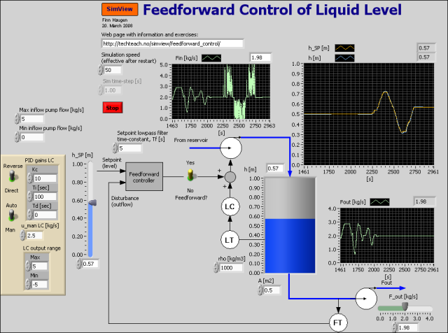
Snapshot of the front panel of the simulator:
- What is needed to run the the simulator? Read to get most recent information!
- Tips for using the simulator.
- The simulator:feedforward_liquid_level_control.exe.
Description of the simulated system
The system being simulated is a level control system based on feedback PI control from level measurement and with the possibility of including feedforward control from outflow (disturbance) and from level setpoint. The simulator is implemented in LabVIEW Simulation Module. The PID controller is the LabVIEW PID Advanced function.
The mathematical model of the process to be controlled is based on mass balance of the contents, which is water, of the tank. The mass balance is as follows:
rho*A*dh(t)/dt = Fin(t) - Fout(t)
Here the inflow Fin(t) is assumed to be the same as the pump control signal u(t), hence both are in unit of kg/s. Solving for the time-derivative gives
dh(t)/dt = [1/(rho*A)]*[u(t) - Fout(t)]
which constitutes the process model written as a state-space model. This model will be the basis of the development of the feedforward control action, cf. the tasks below.
Video
Here is an instructional video where the present simulator is used as an example: Feedforward control.
Aims
The aim of this simulator is to demonstrate the benefit for the level control by using feedforward control in addition to the (compulsory) feedback control.
Motivation
Feedforward control can improve the control substantially, i.e. the control error may become substantially smaller compared to not using feedforward. However, feedforward control may be difficult to implement because a process model is required (in the present example, however, the process model is quite simple), and disturbances have to be measured, implying extra expenses.
Tasks
In all the task below always use feedback control (with PI controller), i.e. set the PI controller in automatic mode. The PI parameter settings can be as shown in the figure above.
1. Deriving the feedforward control function: Assume that the level control setpoint is hSP [m].From the process model given above, show that the feedforward control function is
uf(t) = A*rho*dhSP(t)/dt + Fout(t)
Explain the physical meaning of this feedforward control! Does this control function "make sense"?
You should never implement a pure time-differentiation because the time-derivative is very sensitive to noise and abrupt changes of the signal to be differentiated. In stead, you should implement a smoothed derivative by letting the signal pass through a lowpass filter before the differentiation. According to this we modify the feedforward from setpoint part of our feedforward controller as shown below:
uf(t) = A*rho*dhSP,filt(t)/dt + Fout(t)
where hSP,filt is a lowpass filtered level setpoint. The filter may be a time-constant filter:
hSP,filt(s) = ]1/(Tfs+1)] hSP(s)
where Tf is the filter time-constant. In the simulator the time constant is set to 5 sec.
2. Not using feedforward control:- Adjust the outflow (disturbance) arbitrarily. Observe the level control error.
- Then, adjust the level setpoint arbitrarily, and observe the control error.
3. Using feedforward control:
- By default the output of the feedback controller (PI controller) has only a positive value range, from 0 to 5 kg/s. This non-negative range may imply that the controller is not able to make the control error become zero in steady state after you have activated the feedforward controller. Why not?
- Then, change the minimum output value of the PI controller from 0 to -5. Does this help?
- Adjust the outflow arbitrarily. Is the level control error reduced because of the feedforward control action?
- Then, djust the level setpoint arbitrarily. Is the control error smaller with feedforward control?
Updated 23 April 2021. Developed by Finn Haugen. E-mail: finn@techteach.no.