|

Rigg for turtallsregulering av likestrømsmotor
TechTeach disponerer 4
stk identiske DC-motorrigger for undervisningsformål.
Oversikt
Figur 1 viser
motorriggen, IO-komponent og bærbar PC som kjører en LabVIEW-app utviklet for
turtallsregulering av motoren.
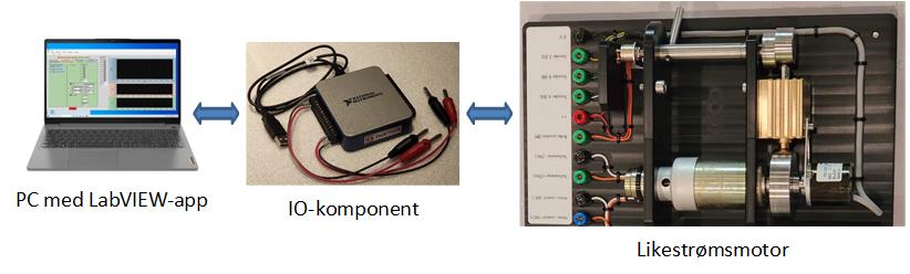
Figur 1: System for turtallsregulering av motor
Beskrivelse av motorriggen
Figur 2 viser
motorriggen.
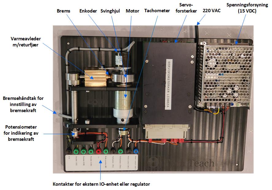
Figur 2: Motorrigg
Beskrivelse av
motorriggen:
·
Motorriggen
kan brukes til hastighetsregulering (turtallsregulering). Også
posisjonsregulering er mulig siden motorens vinkelposisjon måles.
·
Motoren
er en DC-motor fra Faulhaber.
·
Motoren
kan styres med et spenningssignal i området +/- 10 V. (I studentoppgaver
brukes oftest området 0-5 V.)
·
En
kodeskive (encoder) måler både rotasjonsposisjonen og rotasjonshastigheten.
Kodeskiven har en oppløsning på 360 pulser per omdreining.
·
Et
tachometer måler rotasjonshastigheten. Et tachometer er en
likespenningsgenerator som gir en spenning som er proporsjonal med
hastigheten. Proporsjonalfaktoren er angitt i appen som brukes til å styre
motoren.
·
Motoren
kan bremses med en bremsekraft (eller bremsemoment). Bremsekraften kan
justeres med et håndtak. Et potensiometer er montert på stanga med
bremsehåndtaket. Potensiometerspenningen gir en indikasjon på bremsekraften.
Potensiometerspenningen er i området fra 0 V (ingen bremsekraft) til ca. 3 V
(maks bremsekraft). Bremsemålingen kan brukes bl.a. til foroverkopling.
Figur 3 viser et tydeligere
bilde av kontaktene på motorriggen.
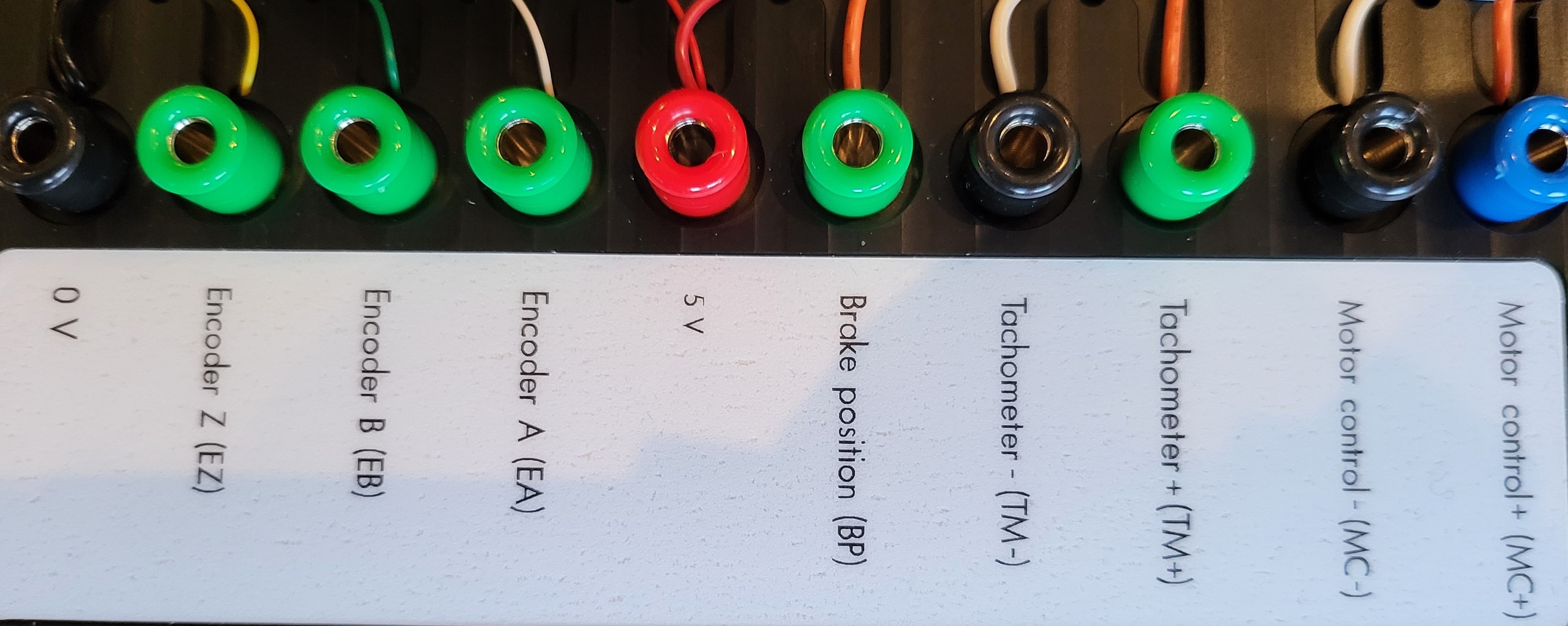
Figur 3: Kontaktene på motorriggen
Teknisk dokumentasjon:
·
Koplingsskjema v/Cody AS, Skien
·
Motor
(kommer)
·
Kodeskive
·
IO-komponenten USB-6001
PC
Til hver rigg er det en
bærbar PC (Acer Inspire) med følgende programvare:
·
LabVIEW
Runtime Engine inkl. NI-DAQmx-drivere
·
Python
(Anaconda-distribusjonen) og Python Control Package
·
OpenOffice
·
Nettleseren
Microsoft Edge
LabVIEW-app
Det er laget en
LabVIEW-app (ikke fritt tilgjengelig) for hastighetsregulering av motoren med
IO-komponenten nevnt ovenfor. Appen forutsetter at LabVIEW Runtime Engine Q3
2022 og NI DAQ Runtime Engine er installert (disse er fritt tilgjengelige fra
ni.com). Appen brukes av TechTeach i undervisning.
Prosessregulator
Prosessregulatoren PXU PID Controller (Red
Lion), som implementerer både en PID-regulator og en av/på-regulator, kan
benyttes til å regulere motoren.
Tema
Med ovennevnte utstyr
og programvare kan riggen brukes til oppgaver om følgende tema:
·
Instrumentering
av reguleringssystem for turtallsregulering
·
Målesignalomregning
fra tachometerspenning til krpm (kilo revolutions per minute)
·
Målesignalomregning
fra enkoderpulstog til krpm
·
Målesignalfiltrering
med tidskonstantfilter og middelverdifilter
·
Manuell
regulering
·
Automatisk
regulering med av/på- regulator
·
Automatisk
regulering med PID-regulator (P, PI, PID)
·
Regulatorinnstilling
(Ziegler-Nichols, Åstrøm-Hägglund (rele-metoden), Good Gain, Skogestad)
·
Foroverkopling
fra turtallsreferanse og prosessforstyrrelse (bremsekraftmåling)
·
Lagring
av dataserier på fil og videre behandling i regneark eller Python
·
Simulering
(ovennevnte app inneholder en simulator som kjører i parallell med den
virkelige motoren). Simulatoren er basert på en «tidskonstant-modell» inkl.
lastmoment i form av en ekvivalent «lastspenning» som er addert til
pådragsspenningen:
S’ = [Ku*u + KL*L – S]/Tm
der S er hastighet, S’ er hastighetens tidsderiverte (endring av S per
tidsenhet), u er pådragsspenning, L er lastspenning, Ku er
pådragsforsterkning, KL er lastspenningsforsterkning og Tm
er motor-tidskonstant.
·
Tilstandsestimering
med Kalman-filter (estimering av lastspenning («lastmoment»))
·
Modelltilpassing
(optimal estimering av modellparametre fra eksperimentelle tidsserier). Til
modelltilpassingen kan en bruke et ferdigutviklet Python-program som
tilpasser modellen ved å finne de verdiene av modellparametrene (f.eks. Km,
Tm og L) som gir beste overensstemmelse mellom eksperimentell og
simulert tidsserie. Med «beste» menes minste sum av kvadratisk avvik
(prediksjonsfeil) mellom de to tidsseriene.
·
Bruk
av industriell prosessregulator (PXU PID Controller, Red Lion).
7.3 2023. Finn
Aakre Haugen (finn@techteach.no).
|